Quick answer
Choose the beam from the fitting-to-page geometry, then test both occupied bed positions. The stated angle describes only part of the light distribution; check page coverage, spill and visible-source glare with the exact sample.
A hotel bedside reading light beam angle should be chosen from the distance and direction between the fitting and the page, then checked from both pillows. A narrower stated angle can concentrate light on a book; a wider one can cover more movement but may spill onto the neighboring guest. Neither number proves reading comfort on its own. Ask for photometric data for the exact optic, test the sample at the proposed mounting point, and assess page coverage, source glare, shadows, and the usable aiming range together.
What the angle actually means
The Illuminating Engineering Society defines beam angle between directions where luminous intensity is half of the beam's maximum. It is a description of distribution, not a hard edge. Light remains outside the stated angle. Some asymmetric fittings need two angles measured in perpendicular planes, so a single catalogue figure may omit useful detail.
Beam angle also differs from the result on a book. The beam footprint changes with distance, aiming, optical construction, and the way a guest holds the page. Wattage is electrical input; it cannot substitute for beam or illuminance data.
Draw the geometry first
Mark the proposed light source, book plane, mattress, pillows, and eye lines on a scaled elevation and section. Estimate the range of positions in which guests may read upright and reclined. A headboard-mounted fitting close to the book does not need the same distribution as a ceiling light farther away.
Use the drawing to shortlist optics, then install a sample. Hold a book at several normal positions. Is the complete page usable, or is there a bright center and dark edge? Does moving the book slightly make the beam disappear? Check the opposite pillow for spill. Record the mounting distance and aiming angle used in the test so another room can reproduce it.
Look beyond the nominal beam
Request an IES photometric file or measured distribution for the exact product and configuration when available. IES guidance on photometric files explains that they describe luminous intensity by direction. Such a file can support design calculations, while the mock-up still tests the visible source, reflections, and real materials.
Check shielding and field spill. A fitting may have a concentrated center yet remain visibly bright from the reader's eye. A wide beam may create an attractive headboard wash but fail to isolate one guest's book. If both ambient and task functions are needed, specify each function separately and verify the controls.
Compare documented MYDE examples carefully
The product fact locks for MD-WL-Y135 and MD-WL-Y003 each state a 30° reading beam and 3 W input. Y135 is recessed with an adjustable head. Y003 is surface-mounted with an adjustable head, a toggle switch, and one USB-A port. The shared angle does not mean the two fittings create identical light distributions in a room. Their mounting positions, surfaces, and optical details still need sample comparison.
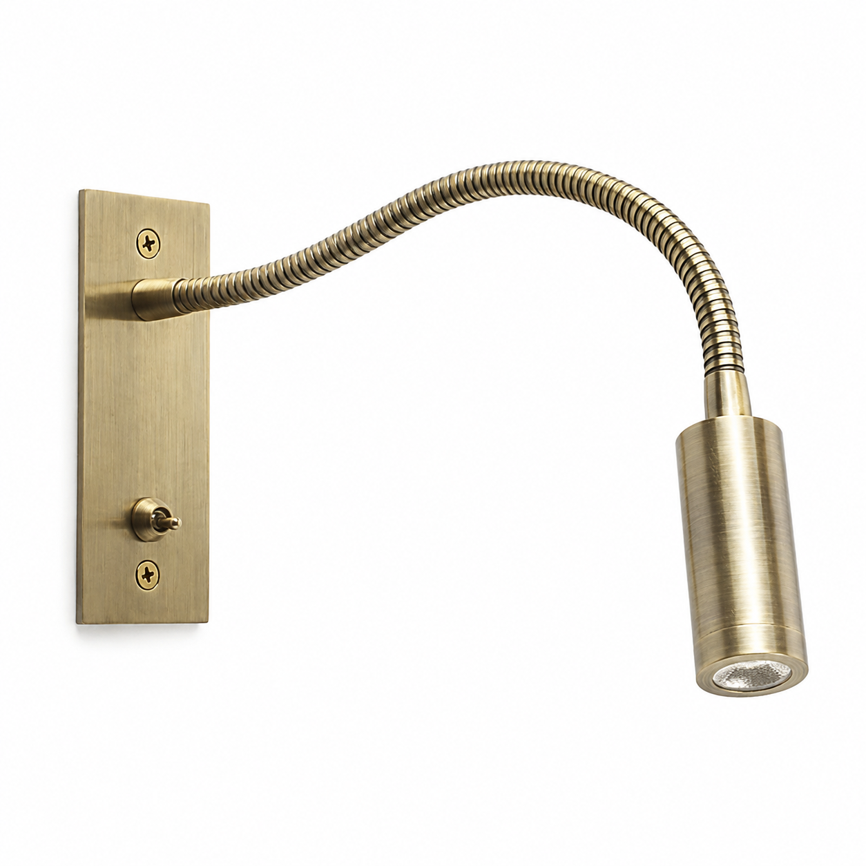
MD-WL-Y092 has a flexible gooseneck, which changes where the head can be placed. Its source pack does not confirm a beam angle. Do not borrow the 30° figure from the other models. Request the specific optical data and test the flexible arm in its useful positions.
Make the approval repeatable
Set the mock-up bed and headboard to the intended dimensions. Test the reading page at both sides with the ambient light on and off. Note page coverage, spill, visible source, switch reach, and the parked position. If the project has a measured illuminance target, have the lighting designer define where and how it is measured. Record the exact model, optic, CCT, driver, mounting coordinates, and approved aiming position. Recheck when any of those changes.