Quick answer
Use one room-by-room schedule to match every light to its mounting point, supply, control, circuit and access detail across all drawings.
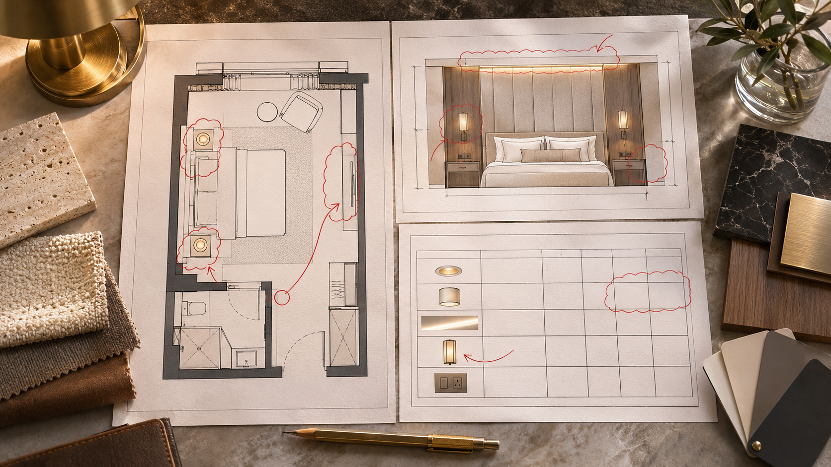
Hotel room lighting coordination with electrical plan means every fixture shown by the designer must have a matching supply, control, mounting point and service path on the electrical set. The mismatch may be small on paper and costly after headboards are installed: a reading light can be drawn on one side of a seam while its cable appears on the other. Review the room type as a single system before rough-in. Use a shared fixture schedule, mark drawing revisions and resolve discrepancies with the qualified electrical and joinery teams rather than leaving them for site interpretation.
Build one reference schedule
Give each light a unique room-type identifier. Record its exact ordered variant, location, mounting, supply, driver, control method and any charging function. Attach the manufacturer's current drawing where an opening or driver space is required. The lighting plan, reflected ceiling plan, headboard elevation and electrical plan should all use that same identifier.
The hotel wall light wiring guide explains the specific fitting handoff. Here the goal is to reconcile the entire room set. A schedule that lists only watts and finishes cannot tell the contractor which switch operates a headboard light or how a driver can be serviced.
Compare physical positions
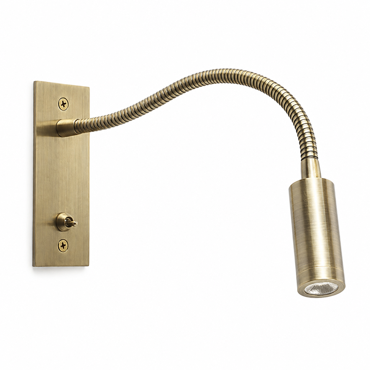
Overlay the bed and furniture elevations with electrical outlets and cable entries. Check door swings, mirrors, upholstery seams and access panels. A surface-mounted MD-WL-Y003 and a recessed MD-WL-Y135 need different installation details; their source packs do not provide a universal cable point. Ask for current drawings of the exact variants and place their true envelopes on the coordinated section.
Confirm the source can be reached from the guest position and that a powered port, if present, sits where its cable can be used without stretching across the bed. A product image does not settle the position of a junction box or outlet. The electrical designer should specify local protection and compliance requirements.
Write the room control matrix
For each fixture, show what happens on arrival, during reading on either side, at night and at all-off. Identify which circuits respond to the room master and which remain supplied. If the design calls for dimming, confirm the exact driver and luminaire support it. The documented Y003 reading head is non-dimmable; placing it on a dimming schedule without a verified alternate configuration would be an error.
Check behavior after a power interruption and during the staff reset sequence where the control supplier provides those functions. Do not assume a switch label is enough; the control system, driver and fitting must be tested as an installed combination.
Close and track conflicts before rough-in
Create a short discrepancy log: drawing references, affected fixture, responsible discipline, decision and revision date. Resolve any item that changes a hole, cable path or control before the wall or headboard is closed. A field change should update all drawing views, not just a contractor's marked-up copy.
Finally, test one complete room. Compare actual operation and maintenance access with the schedule. Record accepted photographs and product versions, then use the same check on repeat rooms. The coordinated plan is an interface agreement among disciplines, not a substitute for qualified electrical design or site inspection.